Week 22: Nov 14th - 20th
- Group Work
- Nov 20, 2022
- 6 min read

Updated: Nov 27, 2022
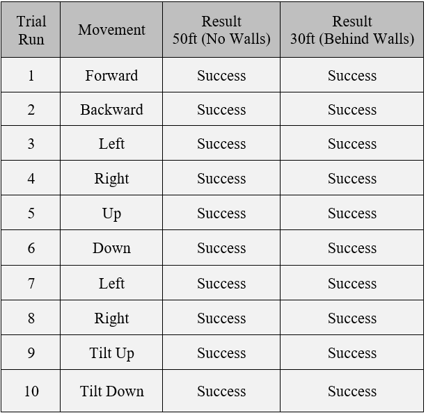
Figure 1: General Test of Movements
Transmitting and Receiving
The transmitting and receiving of this project are based on the performance of the GUI, Bluetooth module, and the Arduino. This requirement includes the testing of the RCMS by positioning the microphone on 5 separate instruments and speaker cabinets. The testing of the Bluetooth module will include maneuvering the RCMS from the nominal range of 50 feet with no walls and 30 feet behind walls with 10 separate trials.
High Level Requirement Testing for Receiver/Hardware:
The first test was to meet the highest-level engineering requirement of the RCMS’s ability to move itself to a particular location and move the microphone to any desired location set by the user. To quantify this test, we placed a small piece of tape to mark the center of the front of the chassis and a marked location near where the instrument would be placed in the shape of a “T” which can be seen in Figure 2.
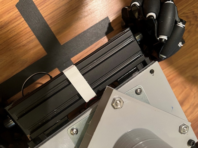
Figure 2: Ground Marker for Positioning Test
Another piece of tape was placed 3.5 feet behind the first ground marker and at an offset of 1.5ft. The RCMS was placed on the second ground marker and in each trial, driven to the ground marker closest to the instrument and the distance between the T-shaped ground marker and the center of the chassis was measured. The objective was to test the chassis movements to have this distance measurement to within 3-inch tolerance. The entire testing setup can be seen in Figure 3.
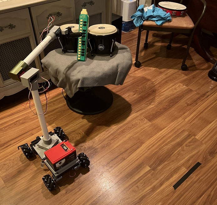
Figure 3: Example of Positioning Test.
The second part of this test was to measure the arm’s ability to position the microphone within a tolerance of 1 inch to the marked location on the instrument such as the one seen in Figure 4. Both tests combined in the same trial assuredly evaluates the ability of the entire RCMS system to place the microphone in any desired position the user would like. It should also be noted that each instrument/amplifier was placed within the height range and arm length.

Figure 4: Example of Instrument Marker for Positioning Test.
Figure 5: Example of Positioning Test
The results shown in Table 1 demonstrate that the RCMS is very capable of positioning itself in any position the user would like with enough precision to be within a small tolerance.
Table 1: Positioning Test (High Level Requirement for Receiver/Hardware)

High Level Requirement Testing for Transmitter/Software:
The next high level engineering requirement of the RCMS is the Bluetooth’s ability to transmit and receive within a range of 50 feet with no walls and 30 feet behind walls. This test was conducted at Valencia College so that we had access to long hallways to test the distance. We first placed the RCMS at about 50 feet by measuring with a laser measuring device which can be seen in Figure 6. After the measurement was taken, each movement was tested to assure that the correct data was being transmitted and received. Figure 7 shows Neil performing the distance test at 81 feet. For the behind walls test, we placed the RCMS in the hallway at about 30 feet from the distance from the closed door and the movements were tested again. A video of the test can be seen in Figure 8.

Figure 6: Measuring Distance for Range Test (No Walls).

Figure 7: Example of Range Test (No Walls).
Figure 8: Example of Bluetooth Range Test.
The results shown in Table 2 demonstrate that the RMCS’s Bluetooth range is well within our set requirement. To test the furthest distance, we also measured the farthest we could drive the RCMS until it lost connection. This distance was measured to be 129.16 feet with no obstruction and 77 feet behind doors. This proved to be greater than our projected range.
Table 2: Bluetooth Range Test (High Level Requirement for Transmitter/Software)
Microphone Positioning, Maneuvering, and Battery Life
Mid Level Requirement Testing for Receiver/Hardware:
Weight:
The system was tested with two different microphones of different weight. The first was at the low end of the weight capacity of the system which is the Shure sm57. This microphone was used for most tests that did not involve weight criteria. The weight of this microphone is approximately 286 grams. The up/down motor and tilt motor have no problems lifting this weight and as mentioned was done extensively in other tests.
The second microphone used was the heaviest microphone available to the team which was a Shure sm7b. This microphone has a weight of 766 grams. The tilt and up/down motors were able to lift this microphone although with some problems. This is to be expected because the weight of this microphone is heavier than the maximum theoretical weight capacity of the system. From these results it can be gathered that the theoretical maximum weight capacity of 680g is very close to the actual weight that can be lifted without issue by the motors.
Height:
The microphone stand was measured at the highest point reachable by the arm and the lowest point reachable by the arm using a tape measure. It was found that the stand could reach 3ft and 11in from the floor at the maximum and 2inches from the floor at the minimum. The theoretical limits were 4ft from floor level and 2in from floor level. The maximum height was one inch away while the minimum height was correct.
Battery Life:
To test for the maximum battery life, the system was left in a position where both the tilt and up/down arm motors were engaged for an extended amount of time. Once the battery indicator showed a change in battery level from full to two-thirds, the time was taken down and the full life of the battery extrapolated from it. The time at which this occurred was 8 hours and 13 minutes. If the system remained in the same position for the rest of the battery life, then the battery could last up to 24 hours and 39 minutes. Typical studio sessions can range from a couple of hours to twelve hours so this system would last up to two sessions before a charge is needed.
Mid Level Requirement Testing for Transmitter/Software:
Preset Functionality:
To test the preset functionality of the RCMS, 6 random positions were saved as presets and recalled from a nominal position of 90 degrees on each servo motor in the arm portion. Table 3 shows the stored positions and the recalled positions of the arm. These results in show that the RCMS GUI can save positions and recall them and have the Arduino move the arm exactly to those saved positions. A video of the test is shown in Figure 9.
Figure 9: Example of Preset Functionality Test.
Table 3: Testing High Level Requirement for Hardware/Reciever

Microphone Position Display and Cable Management
Low Level Requirement Testing for Receiver/Hardware
Cable Management:
To test the cable management system, which consists of a piece of acrylic tubing attached to the back of the chassis in which the microphone cable in run, a test of the chassis movement in every direction was conducted. The chassis was moved three feet in each direction it is capable of movement and observed for cable entanglement. The cable management system was successful in keeping the cable out of the way of the moving chassis in each movement within a tolerance of a foot. As this system is intended for small movements, the chassis would likely never move as much as in this test, but each trial was a success, nonetheless.
Low Level Requirement Testing for Transmitter/Software:
Position Display:
The objective of this test was to ensure that the positions displayed on the GUI matched the positions of the RCMS arm portion. Simple angles were chosen to make it obvious that the angles were correct such as when the arm is pointing directly in front of the chassis or 45 or 90 degrees from the center of the chassis. Since the center angle is 135 degrees, a 45 degree angle from the center would be either 180 or 90 degrees. Figure 10 shows that the arm is pointed 45 degrees right from the center and the up/down portion and tilt portion are pointing 45 degrees up from the center. By comparing the actual position of the arm portion to the displayed values in the GUI it can be observed that they are consistent. These results can be seen in Table 4.
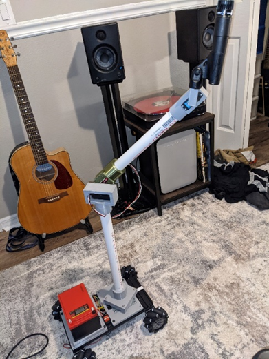
Figure 10: a.) Actual Arm Position

Figure 10: b.) Displayed Arm Position
Table 4: Position Display Test (Low Level Requirement)
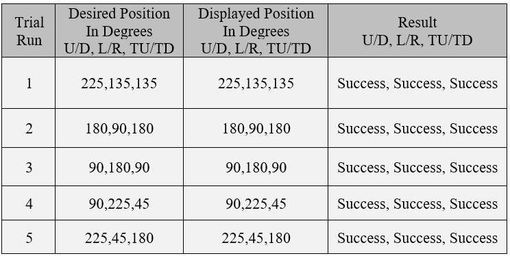
The results shown in Table 4 demonstrate that the desired angles match the displayed values within enough accuracy that the user would know in reference to the displayed values where the arm portion is relative to the chassis. This proves that the RCMS is not only accurate but also can move to greater angles than originally intended.
Summary:
After testing was concluded the RCMS met all the requirements set out in the engineering requirements section. It can lift the required weight, it exceeded the required battery life, its capable of maneuvering to any desired position with a displayed accuracy and exceeded the required Bluetooth range. The preset feature of the GUI proved to function as intended as well.

Comments